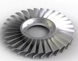
In recent years, foreign aviation countries have adopted the integral blade-disk structure, merging the blade and disk into one piece, eliminating the tenon, groove, and locking device. This eliminates the airflow loss caused by the tenon, reduces the structural weight, and minimizes the number of parts. In the aerodynamic layout, the design uses wide-chord, curved blades, and narrow flow channels, which improves aerodynamic efficiency. Engineers simplified the engine structure, enhancing the thrust-to-weight ratio and reliability of the blade disk in the new fighter’s high-thrust engines.
Current status of black manufacturing technology at home and abroad
Currently, foreign countries use three typical structures of black structures, as shown in Figure 1.
(a) Closed structure—integrated black with hoop;
(b) Open structure—integrated black without hoop;
(c) The structure of the large and small blade rotors positions the small blades between the large blades in an open structure.

Figure 1 Three typical integral blade disc structures
The integral blade disc, a high-speed rotating component, requires weight reduction, precise balance, and improved fatigue strength. Manufacturers use difficult-to-process materials like titanium and high-temperature alloys, ensuring no cracks or defects through strict non-destructive testing. With thin, long, and twisted blades, the disc is prone to deformation under force. The channels between the blades are deep and narrow, and the openness is very poor. Therefore, manufacturing and maintaining the integral blade disc is particularly difficult, and foreign countries strictly seal this core technology.
The main processes used in the manufacture of integral blade discs abroad are precision forging blank + precision CNC machining; welding blank + precision CNC machining; high-temperature alloy integral precision casting blank + hot isostatic pressing treatment, etc. Because CNC machining has the characteristics of rapid response and high reliability, GE and P. W companies in the United States, R. R Company in the United Kingdom, etc., used five-axis CNC machining technology when developing integral blade discs. The material removal rate exceeds 90%, with high technical difficulty, reflecting the latest and highest level of international CNC machining technology. The NREC launched the MAXCAM system, the most famous related software.
China has also conducted a lot of research on the software and key processing technologies related to the overall impeller blade. Northwestern Polytechnical University has developed a “special software system for multi-coordinate NC programming of impeller parts”. The system integrates measurement data preprocessing, surface modeling, surface hiding, tool position calculation, tool position verification, and post-processing. It has played a key role in developing and producing more than 20 impeller blades.
The manufacturing process of the integral blade disk
This paper proposes a composite manufacturing process for integral blade disks by analyzing their structural characteristics and manufacturing requirements. The process includes producing near-forming blanks, precision forming, surface inspection, and polishing. In each stage, we select typical methods and adjust the process integration scheme based on the blade complexity. We then choose the mature and stable process combination.
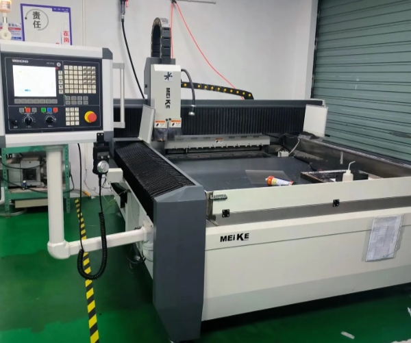
The manufacturing of integral blade disks involves producing near-forming blanks, precision forming, surface inspection, and polishing. The blade disk, a key force-bearing component, must meet strength requirements. Larger sizes are typically made by integral forging or welding. The process starts with forging the initial blank, followed by near-forming using efficient CNC methods like electrolytic machining, wire cutting, and milling.
Welded blanks have the advantages of saving materials and being suitable for manufacturing dual-performance disks. They can manufacture nearly formed blanks with good openness, small blade distortion, simple shapes, and without hoop integral blade disks. However, China currently lacks mature technology, and challenges such as welding stress and deformation, structural changes, and defect control need to be addressed.
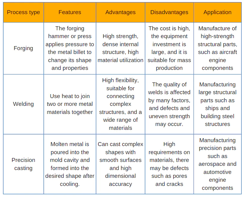
In the stage of precise forming, we can use electrolytic machining and integral CNC milling. The electrolytic machining process eliminates mechanical cutting force and reduces machining stress, making it ideal for difficult-to-machine materials and complex details. Researchers need to conduct further studies to solve problems such as the electro-etching layer and finishing. The CNC milling process uses the five-axis motion envelope of the milling cutter to mill the flow channel shape. This process is ideal for manufacturing integrally closed blades and other complex curved integral blades.
Recommended Approach for R&D and Small-Scale Production
A feasible approach for R&D and small-scale trial production in China is using “isothermal forging + high-efficiency, low-stress rough machining” for near-forming blanks, reducing margin to shorten processing cycles, and employing five-axis CNC milling for precision.
This process responds rapidly, requires less special process equipment, has more mature technology, and manufactures qualified blades. Therefore, this process is an ideal choice for the research and development and small-scale trial production stages. After completing the CNC milling of the blade, you can use abrasive flow or vibration finishing methods to improve the surface finish and integrity.
Key technologies for CNC machining of integral blade disks
(1) Channel analysis and division of machining areas
To determine the processability and tool accessibility of CNC machining blade disks, the channel characteristics must be analyzed first. The analysis provides key information for determining CNC tool parameters, machining processes, or evaluating manufacturability. It includes the narrowest width, constraint state, blade properties (e.g., ruled or free-form surface), torsion, section thickness, edge size changes, fillet radius, and machining feasibility. The tool in Figure 2(a) is accessible for machining, while the tool in Figure 2(b) is not, preventing part completion.

Figure 2 Channel machining feasibility analysis and docking area division
Due to constraints in adjacent blades, rings, or tool rigidity, five-axis CNC equipment often requires double-sided docking. Reasonably dividing the machining area (Fig. 2 (c)) shortens tool length, increases rigidity, and improves efficiency, ensuring both ends have similar and minimized lengths.
(2) Determination of the optimal tool axis direction and smoothing treatment
The blade curvature of the integral blade varies greatly, and its machining is under a multi-constraint state. In tool trajectory calculation, determining the tool axis direction is crucial for interference-free and efficient machining. As shown in Figure 3, the required tool length varies significantly for the same point on the blade inside the channel depending on the tool axis direction.
Using a fixed cutter axis for side milling requires a very long tool, significantly reducing rigidity and cutting efficiency. When using a variable cutter axis for point contact processing, the tool length shortens as the angle between the cutter axis and the blade disc axis decreases. The optimal cutter axis direction minimizes this angle while avoiding interference with the surrounding channel, ensuring maximum rigidity and efficiency.
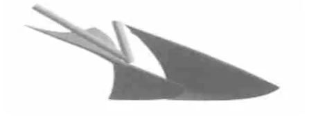
Figure 3 Effect of tool axis direction on tool length
Challenges of Tool Axis Direction Change in Multi-Constraint Machining
Due to multi-constraints, the tool axis direction between adjacent positions may change discontinuously, as shown in Figure 4.
A sudden change in the tool axis direction can cause rapid speed changes due to the rotation of the five-axis CNC machine table or spindle swing. This results in a sudden change in the cutting force of the tool. The machining process can deteriorate the part’s surface quality or damage the tool blade.
To ensure there is no interference or collision during machining, we need to further smooth the initial vector of the optimal tool axis direction. To prevent the tool from interfering with the channel, you must perform this smoothing under multi-constrained conditions. We must verify the tool trajectory and perform interference collision checks to confirm the accuracy of the tool position calculation. This includes checking whether the toolbar interferes with the surrounding channel and whether the tool handle and spindle head collide with the workpiece or fixture.
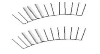
Figure 4 Comparison of tool axis directions before and after smoothing
(3) Efficient rough machining technology for blade disc channel
In the process of machining the entire blade disc from blank to finished product, the rough machining stage of the blade disc channel removes about 90% of the material. Therefore, efficient rough machining is the key to improving machining efficiency and shortening the manufacturing cycle.
We developed efficient channel rough machining methods by analyzing properties, optimizing tool axes, calculating contour trajectories, performing anti-interference checks, simulating dynamics, and controlling tool vibrations.
Due to the large amount of material removal, the blade disc generates large cutting stress after rough machining. To control the deformation caused by rough machining stress, we adopt the following three methods:
a. Reduce the cutting stress during machining by optimizing the tool and process parameters and optimizing the contact state between the tool and the workpiece;
b. Eliminate the cutting stress through the heat treatment process to reduce the later deformation;
c.Use the method of dispersing the process and repairing the benchmark multiple times to compensate for the deformation error. These measures not only control blade disk deformation but also reduce the near-formed blank allowance, significantly shortening the machining cycle.
(4) Precision machining technology of blade profile
The precision machining of the integral blade disc involves machining features such as the inner ring, outer ring, blade profile, leading and trailing edges, and blade root transition zone. The wizard diagram based on an AND/OR tree represents the machining process and machining sequence of the integral blade disc. It describes the process characteristics, conditions for determining the machining sequence, and the corresponding machining processes and tool path generation methods for each feature.
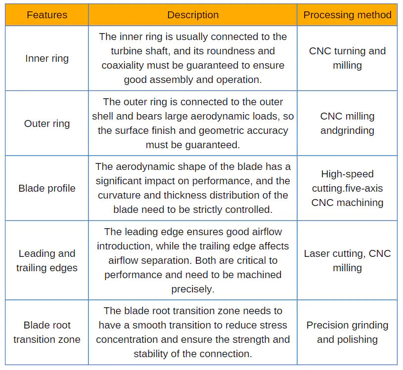
The inner and outer rings are CNC turned; the closed blade disk surface and open blade disk (including rotors) are CNC machined on critical surfaces using five-axis CNC; the blade root transition zone is cleaned with a “radius decreasing” solution.
The blades of the integral blade disk are very thin, with the blade tip and leading/trailing edges less than 0.4mm. Cutting forces cause blade vibration, leading to serious “cutting back” issues. Tool vibration, caused by the limited channel, small tool diameter, and long tool rod, along with blade vibration, severely affects surface quality, leading to fish scale defects and incomplete blade tip processing.
Researchers use three methods—finite element analysis, force measurement, and coupling analysis—to solve the blade-tool chatter problem.
a. Determine the optimal tool contact position to reduce total cutting force and chatter-causing components.
b. Determine tool parameters based on part rigidity to match blade and tool stiffness.
c. Enhance blade rigidity and increase chatter damping to control amplitude during cutting using the filling method.
Our experiments confirm that these measures effectively suppress chatter and ensure blade accuracy and surface quality.
Conclusion
This paper proposes a composite manufacturing process for the integral blade disk, based on its structure and existing domestic processes. It discusses key technologies, and solutions to challenges, and summarizes engineering experience in CNC machining of the integral blade disk.
We have successfully applied the proposed method in model development. We completed machining the first and second-stage fan blade disks of a turbofan engine, along with the rotor test pieces of a turboshaft engine, achieving the expected test results. Figure 5 shows the completed first stage fan blade disk. After CMM inspection, we control the blade profile error to 0.05mm and blade disk deformation to 0.04mm, fully meeting design requirements.
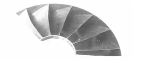
Figure 5: Integral blade disk sample

