In modern manufacturing industry, trapezoidal thread, as an important transmission element, is widely used in mechanical equipment, automation systems and all kinds of industrial products, and its machining accuracy and surface quality directly affect the performance and service life of the equipment.
Therefore, how to efficiently and accurately process trapezoidal threads has become an important issue in the field of machining. With the rapid development of CNC technology, macro program, as a powerful programming tool, gradually shows its unique advantages in complex workpiece machining.
Macro program can not only simplify the programming process, but also realize the automation and intelligent management in the machining process, so as to improve the production efficiency and product quality.
In trapezoidal thread machining, the application of macro programs can effectively solve many problems existing in the traditional machining methods, such as tool wear compensation, size control, process parameter optimization.
Machining process analysis
1. Workpiece clamping
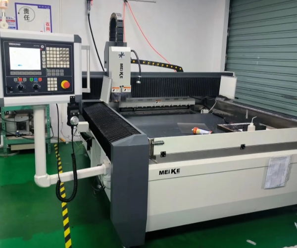
When machining Tr32×6-7e (OD 32mm, pitch 6mm) trapezoidal threaded parts (Figure 1), the clamping of the workpiece is critical. For this reason, the operator uses the clamping method of one clamp and one top to ensure the stability and symmetry of the workpiece during the machining process.
Specifically, the operator first uses the three-jaw self-centering chuck for direct clamping and places the workpiece in the center of the chuck, aligning it with the jaws.
Secondly, rotate the chuck handle, the three jaws uniformly inward contraction, the workpiece firmly clamped to ensure that the clamping force distribution is uniform, to prevent deformation due to uneven force in the cutting process.
At the same time, the operator places a top support at the other end of the workpiece to provide additional stability.
In this process, the application of macro programs can automate the clamping process. For example, a macro program can control the chuck’s clamping force and clamping sequence to ensure that the clamping process parameters meet preset criteria.
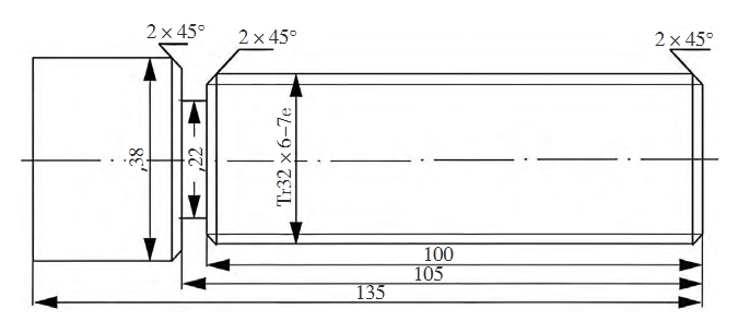
Fig. 1 Trapezoidal threaded part
2. Tool selection and installation
In this machining process, since the trapezoidal thread, as a transmission thread, requires high precision and correspondingly high machining requirements, the operator should use different tool configurations for rough and finish turning.
For this reason, we select the tool configuration combining alloy indexable inserts and machine clamped toolholder to achieve high efficiency cutting performance and good wear resistance.
When installing the tool, you need to pay special attention to the height relationship between the cutting edge of the tool and the axis of the workpiece.
Align the cutting edge of the tool with the axis of the workpiece. If you use a flexible toolholder, ensure that the tool is positioned about 0.2mm above the axis to avoid unnecessary errors during the cutting process.
Macro programs can be used to automate the detection and adjustment of the tool height during the tool setting process. For example, by writing a macro program, the system can automatically measure the height difference between the tool and the workpiece axis and automatically adjust the tool position according to the set parameters.
3. Work step division
> Roughing
The three-jaw self-centering chuck ensures that the workpiece maintains a stable center position during turning, reduces vibration, and improves machining accuracy. The 108mm extended length is set to account for the depth of cut and machining range of the tool.
Use the sample plate for tool alignment to ensure the tool is installed in an accurate position. This helps improve machining accuracy and avoid machining errors in the workpiece caused by improper tool positioning.
External round machining is a key step to ensure the external dimensions of the workpiece, and the 93° tool angle is suitable for external round machining.
At the same time, the 2×45° chamfering process avoids sharp edges and improves the safety and aesthetics of the workpiece. The grooving process is used to form a backing groove for subsequent machining.
A 5 mm wide grooving tool is suitable for this type of machining, and the 2 x 45° chamfers on the left and right side of the tool also improve the accuracy and safety of the workpiece. In the roughing phase, macro programs can be used to automate the setting and adjustment of cutting parameters.
By writing a macro program, you can automatically select the appropriate cutting speed, feed, and depth of cut based on the material and shape of the workpiece.
> Finishing
The quality inspection of threads is an important part of ensuring that the product meets the design standards. This step usually involves the use of thread gauges or other measuring tools to check the thread’s OD, ID, tooth type and other parameters to ensure that the quality is qualified to avoid problems in subsequent machining.
Calculation of tool wear is an important indicator for evaluating the performance of the tool. By regularly checking the wear value, you can understand the tool life and replace or resharpen the tool if necessary to avoid poor machining due to excessive tool wear.
In the finishing process, you can use macro programs to automate quality inspection and tool wear monitoring. For example, you can write a macro program to automatically record the thread parameters after each machining and compare them with the set standards to provide timely feedback on the machining quality.
At the same time, the macro program can also automatically calculate the wear value according to the use of the tool and prompt the operator to replace or repair the tool.
Programming design
In the processing of trapezoidal threads, the layered turning method effectively controls the cutting depth and cutting force. In programming, you divide the trapezoidal thread groove into several layers, and set the cutting amount for each layer reasonably based on the material characteristics and tool conditions.
During the roughing stage, you manage the large cutting volume by dividing each layer into left and right passes. For large-lead threads, you can extend the strategy to three passes—center, left, and right.
This approach balances tool load effectively, reduces wear, and enhances machining quality.
Variable Programming Parameters of Trapezoidal Thread Macro Program
1. Variable Definition and Assignment
In macro programming, defining and assigning variables is fundamental for achieving flexible machining. Variables commonly represent parameters such as:
- Depth of cut
- Feed rate
- Tool radius
- Pitch
These variables enable customization and logic control in the machining process.
2. G65 Macro Program Call Format (FANUC CNC Lathe)
In FANUC systems, you usually call the macro program using the G65 command.
Format:G65P<program_number>L<repeat_times>A<var1>B<var2>C<var3>I<var4>J<var5>
Parameter meanings:
P: Macro program numberL: Number of repetitions (1–9999; default is 1)A, B, C, I, J: Assigned values to local variables in the macro
Example:G65P100L1A2B150C5
→ Calls macro 100 once, with A=2, B=150, C=5.
3. Variable Logic and Operations
Macro programs can perform various:
- Arithmetic operations:
+,-,*,/ - Logical conditions:
IF,WHILE, etc.
This allows execution of complex machining logic.
4. Variable Roles in Trapezoidal Thread Machining
For trapezoidal threads, variable definitions impact machining precision and efficiency:
| Variable | # | Description | Value | Impact |
|---|---|---|---|---|
| A | #1 | Thread major diameter | 32 | Affects cutting path and tool selection |
| B | #2 | Thread lead | 6.0 | Determines pitch and efficiency |
| C | #3 | Tool width | 1.7 | Influences cutting force and surface quality |
| I | #4 | X-direction feed per pass | 0.5 | Affects surface quality and speed |
| J | #5 | Z-direction feed per pass | 1.2 | Impacts thread depth and accuracy |
| – | #6–#13 | Additional geometric and tool parameters | – | Not assigned, calculated or reserved |
| – | #14 | Reserved for expansion | – | Future use |
5. Sample Program for Trapezoidal Thread Machining
%o Trapezoidal thread machining program
M03 S200 ;
M06 T0101 ;
G00 X40 Z6 M08 ;
G65 P0022 A32 B6 C1.7 I0.5 J1.2 ;
G00 X50 Z6 ;
M30 ;
%

%o0022 ;
#6 = #1 - #2 / 2 ;
IF [#2 GE 6] GOTO 10 ;
#7 = 0.25 ;
GOTO 12 ;
N10 IF [#2 GE 14] GOTO 12 ;
#7 = 0.5 ;
GOTO 12 ;
N11 #7 = L ;
N12 #8 = #2 / 2 + #7 ;
#9 = #1 - 2 * #8 ;
#12 = #1 ;
Trapezoidal Thread Measurement and Dimension Control Methods
1. Thread Plugging Gauge Measurement
(1) Roughing Post Inspection : After completing the rough machining of the trapezoidal threads, the first thing to do is to use the through gauge for the Measurement. The through gauge is designed to check whether the maximum outside diameter of the thread meets the requirement. If the through-gauge passes smoothly, it means that the outside diameter of the thread is within the permissible range.
(2) Stop Gauge Inspection: The stop gauge is used for inspection. The purpose of the stop gauge is to check the minimum outside diameter of the thread to ensure that it does not exceed the minimum limit. If the stop gauge fails to pass, the outer diameter of the thread is too small, which will result in a poor fit.
(3) Parameter Adjustment: If the trapezoidal thread fails to pass the through-gauge, you need to adjust the wear compensation parameters of the machine tool. You do this by modifying the relevant parameters in the macro program and re-running the machining program.
The adjustment process consists of checking the tool wear and evaluating its impact on the machined dimensions. Adjust the tool compensation value to ensure that the tool can achieve the desired size when machining.
(4) Re-machining and re-measurement : After adjusting the tool parameters, re-run the machining program and take measurements again. An example macro program is shown below.
iF Through Gauge Pass =FALSE THEN
Adjust Tool Compensation = Calculate Tool Wear
Run the machining program
END iF
2. Three-Pin Measurement
(1) Preparing the Measuring Tool : Prepare 3 measuring pins with the same diameter. Make sure that the diameter of the measuring needles matches the design requirements of the trapezoidal thread.
(2) Place the measuring needles: Place the 3 measuring needles in the corresponding spiral grooves of the trapezoidal thread. The needles should be placed in such a way that they make good contact with the thread to ensure the accuracy of the measurement.
(3) Measure the distance between the vertices: Use a micrometer to measure the distance between the vertices of the measuring pins, M. This distance is an important basis for calculating the center diameter of the trapezoidal thread.
(4) Calculation of the center diameter: You obtain the center diameter of the trapezoidal thread indirectly by measuring the distance M. If the measurement result does not meet the center diameter of the trapezoidal thread, you will calculate the center diameter.
If the measurement result does not reach the design size of the trapezoidal thread, you will adjust the wear compensation value of the X-axis based on the size of the M value. The specific calculation formula is as follows.
M=d2 +4.864dD-1.866P (1)
where d2 is the center diameter of the thread, dD is the diameter of the measuring pin and P is the pitch.
(5) Adjustment of wear compensation: According to the calculated M value, set the corresponding wear compensation value. If the M value is larger than the design value, it is necessary to reduce the compensation value of X-axis in the machining program to ensure that the subsequent machining can meet the design requirements. The example macro program is as follows.
M= Distance of measuring pin apex
iF M> design value THEN
X-axis wear compensation = X-axis wear compensation – (M- design value)
END iF
3. Single pin measurement
(1) Prepare measuring tool: Choose a suitable measuring pin and make sure its diameter is in accordance with the design requirements of the trapezoidal thread.
(2) Measurement of A-value: Place the measuring needle at the suitable position of the trapezoidal thread to measure the dimension, called the A-value, which directly affects the subsequent dimension control.
(3) Size adjustment: If the A value measured after rough machining is not up to the design size, according to the size of the A value, set 2 times of the difference in the X-direction tool wear compensation parameter of the CNC lathe for adjustment.
(4) Calculate the relationship between the A value and the thread size: The relationship between the measured distance A and the top diameter and nominal size of the thread is expressed by the formula (2).
A=2 (M+d0) (2)
where d0 is the actual measured outside diameter of the workpiece and M is the nominal diameter of the thread.
(5) Example analysis: For example, if the A value measured after rough machining is 0.2mm larger than the top diameter of the thread, you should set the X-axis tool wear compensation parameter to subtract 0.4mm. You can effectively adjust subsequent machining to ensure that the final product meets the design requirements. An example macro program is shown below.
A= Measured value
iF A> Design size THEN
X-axis wear compensation = X-axis wear compensation -2*(A- Design size)
END iF
4. Direct Measurement
(1) Prepare the measuring tool: Choose suitable vernier calipers or micrometers, and make sure that their accuracy meets the measurement requirements.
(2) Measure the outer diameter: Place the measuring claw of the vernier caliper or micrometer on the outer side of the trapezoidal thread, clamp it gently and read the value of the outer diameter of the thread.
(3) Measure the inner diameter : Similarly, place the measuring tool on the inner side of the trapezoidal thread, clamp it and read the value of the inner diameter.
(4) Calculation of the center diameter : The center diameter of the trapezoidal thread is calculated from the measured outer and inner diameters.
(5) Dimensional control: Compare the OD and ID values obtained by direct measurement with the design requirements. The macro program example is as follows.
OD = Measured OD value
ID = Measured ID value
ID = (OD + ID)/2
iF ID ! = Designed ID THEN
Adjust tool wear compensation
END iF
Conclusion
The application of macro program in trapezoidal thread machining not only enhances the automation and intelligence level of the machining process, but also provides a strong guarantee for the improvement of product quality.
By reasonably analyzing and designing the machining process, combined with effective measurement and control methods, you can ensure the machining accuracy and consistency of trapezoidal threads.