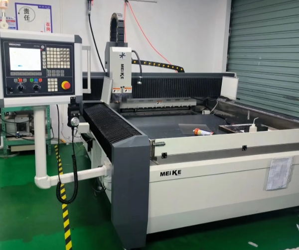
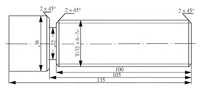
Rapid prototyping, known as layer processing, uses the discrete-accumulation molding principle. Its basic principle is to slice the model in layers according to the three-dimensional (CAD) model to obtain the contours of each layer’s cross-section. A computer-controlled laser beam solidifies layers of liquid photosensitive resin, cuts layers of paper, sinters layers of powdered materials, or selectively sprays layers of hot-melt materials using a certain heat source, according to the cross-sectional contour. This process forms various cross-sections and gradually stacks them into three-dimensional products. The layer processing method does not require traditional machining machines and molds, bringing design work into a new realm, improving human-computer interaction in the design process, and shortening the product development cycle.
Rapid prototyping technology production process
The process of rapid prototyping technology is shown in Figure 1.
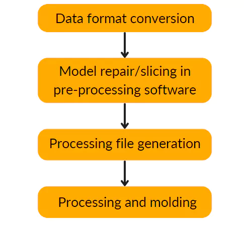
Figure 1 Rapid prototyping process flow chart
Rapid prototyping of rearview mirror
1. Data format conversion
Rapid prototyping equipment can currently accept multiple data formats, such as STL, SLC, CLI, RPI, LEAF, SIF, etc. 3D Systems in the United States developed the STL file format, which most rapid prototyping machines can accept. As a result, the industry considers it the current standard for rapid prototyping data. Almost all types of rapid prototyping systems use the STL format.
Taking the rearview mirror as an example, the preliminary work has completed data acquisition using a three-coordinate measuring machine, point cloud data preprocessing, and surface construction using Imageware software.
The default format of Imageware is *.imw. Typical CAD software systems can directly convert files into STL format in other formats. The system directly saves the rearview mirror model in STL file format.
The model of the CAD solid data model after triangular meshing is the STL file, which is similar to the finite element meshing of the solid data model. The converted STL data model is a data model that uses many spatial triangular facets to approximate the original CAD solid model, as shown in Figure 2.

Figure 2 Three-dimensional model displayed in STL format
2. Data repair
Due to the problems of CAD software and STL file format itself and errors caused by the conversion process, the generated STL files inevitably have a small number of defects. The most common ones are as follows:
1) Triangles that violate the common vertex rule appear;
2) Triangles that violate the orientation rule appear;
3) Incorrect cracks or holes appear;
4) Too many or too few triangles;
5) Omission or error of small features.
You should repair the errors before processing with the rapid prototyping machine. Otherwise, errors may occur during subsequent model slicing or file conversion, resulting in pre-processing or processing failure. Magic software, developed by Materialise, Belgium, is a special software for processing STL format data files and slicing and layering developed for rapid prototyping manufacturing processes. It has functions such as surface repair and automatic support generation, which can quickly and easily repair errors in files.
First, import the file into Magic software and check the properties to find that there are many errors, as shown in Figure 3 (a). From Figure 3 (a), we can see that there are 4,152 bad edges and 142 bad contours. The Fix Tool Sheet module fixed these errors. First, I used the automatic repair (Auto) command, set the number of iterations to 5, and adjusted the stitching width to 0.5. After executing Do All, as shown in Figure 3(b), there were 46 bad edges and 7 bad contours. We then performed manual repairs to fix all the damages. The result is shown in Figure 3(c).
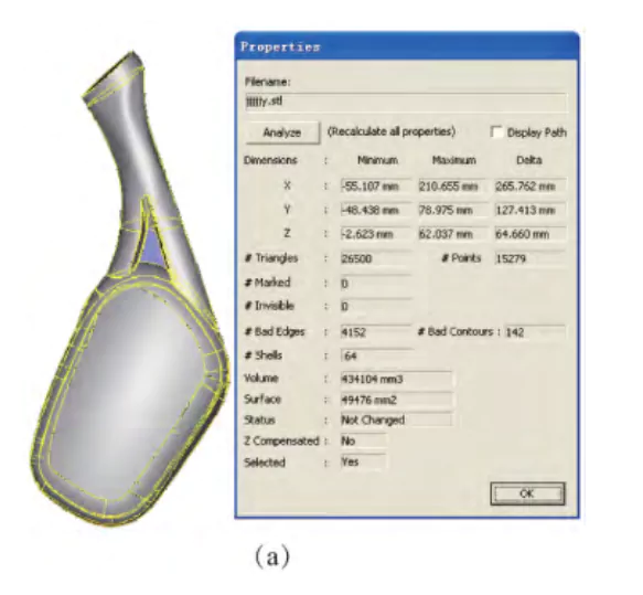
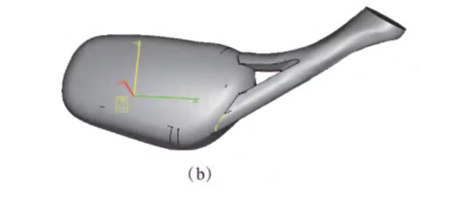

Figure 3 Magic repairs model errors
3. Influence of rapid prototyping parameters
For SLA and FDM rapid prototyping processes that require design support, Magic software provides the function of automatically applying support and slicing. Sintering rapid prototyping generally does not require adding support, and the work done in Magic software involves slicing.
(1) Model placement
According to the requirements of the model structure size and accuracy, considering the efficiency of model production, it is necessary to determine a relatively reasonable placement orientation. For the processing of multi-bevel workpieces, the solution to ensure accuracy is to use the direction with the least bevel as the processing orientation.
The processing direction in the software defaults to the z-coordinate axis direction. Considering the characteristics of the rearview mirror and the direction with the least bevel, we determine the placement orientation as shown in Figure 4.
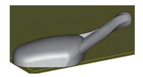
Figure 4 Model placement
(2) Slicing
Since rapid prototyping processes the model layer by layer according to its cross-sectional shape, it requires slicing the 3D model along the height direction at certain intervals before processing to extract the model’s contours. A theoretical defect of rapid prototyping technology is the generation of a principle error-step effect when creating the prototype, as shown in Figure 5.
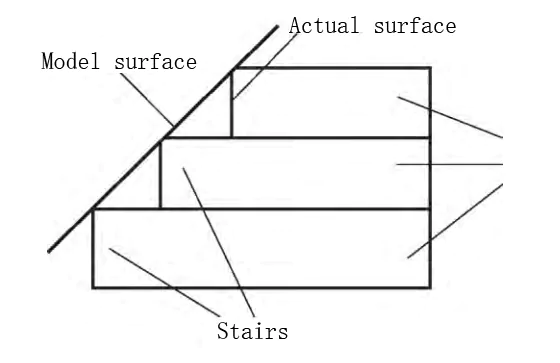
Figure 5 Step effect
The size of the interval is selected according to the requirements of the precision and productivity of the molded part. The smaller the interval, the higher the precision, but the longer the molding time, otherwise the opposite. The interval generally ranges from 0.1 mm to 0.3 mm, with 0.2 mm being the most commonly used. This value typically results in a relatively smooth molding surface.
The slice thickness of this part is 0.2 mm. Figure 6 is the parameter setting dialog box when slicing the rearview mirror file.
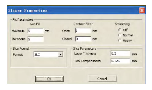
Figure 6 Parameter Setting Dialog Box
After the slice file is generated, it is automatically saved as a file with the same name in the SLC format. Next, import it into the software attached to the rapid prototyping machine to set the molding parameters.
4. Rapid prototyping
The SLS method molds the material by using a laser beam to scan the powdered molding material in layers. The laser beam irradiates the powder, sintering it. After completing the scanning and sintering of the previous layer, the system drops the workbench by one layer of thickness, and the applicator roller applies a uniform, dense layer of powder. Then, it starts scanning and sintering the next layer. This process repeats until the entire model is created.
The commonly used materials for the ASF-320 laser rapid automatic prototyping machine are precision casting wax powder, PS powder, nylon powder, coated ceramic powder, and coated metal powder. The material used here is PS powder, also called polystyrene powder.
After setting all the parameters, the system automatically completes the sintering and stacking process of all the cut layers of the prototype according to the given process parameters (Table 1).
Table 1 PS powder laser sintering parameter optimization configuration

After forming, we need to post-cure, repair, polish, and treat the surface of some parts, collectively referred to as post-processing. After completing these processes, we present the sample in Figure 8.
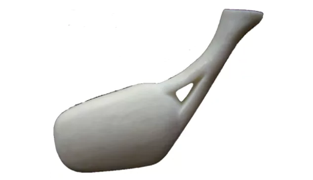
Figure 8 Rearview mirror sample
Conclusion
After completing the surface reconstruction of the physical sample, one option for its subsequent application is to use rapid prototyping technology to manufacture the prototype, use Magic software to process the STL format data file, and perform rapid prototyping on the ASF-320 laser rapid automatic prototyping machine. This avoids the long cycle and complex process design of mechanical processing, so it has important practical significance for shortening the product development cycle, reducing development costs, and improving market competitiveness.


