With the development of modern technology, the improvement of production efficiency, and the advent of non-contact measurement technology, customers are pursuing higher and higher quality.
Measurement is a very important part of quality control, which requires that the measurement technique should also be efficient, accurate and non-invasive.
Traditional vernier calipers, micrometers and other contact gauges gauges are inefficient and unstable, and because the gauges are in direct contact with the surface of the workpiece, it is inevitable that they will cause damage to the workpiece or the gauge.
This has led to the emergence of non-contact measurement technology.
After a long period of development, more and more types of non-contact measurement techniques have appeared.These techniques are mainly based on optoelectronic, electromagnetic, and ultrasonic technologies.
Researchers have developed a wide variety of optical and non-optical non-contact measurement techniques. Examples include nuclear magnetic resonance, X-ray scanning, eddy current measurement, and structured light.
Other techniques include laser triangulation, laser ranging, interferometric measurement, and stereoscopic vision.Ultrasonic ranging is another non-contact measurement technique that has emerged.
In this paper, the two categories of non-contact measurement technology optical method and non-optical method to do a brief description, but also gives examples of the corresponding part of the product, so that engineers and technicians can have a rough understanding of non-contact measurement technology.
Current situation
1. Non-optical method
1.1 Acoustic measurement method
Acoustic measurement method is mainly used for distance measurement, in which ultrasonic distance measurement technology is more widely used. Ultrasonic waves are mechanical waves with a frequency higher than 20Hz.
To use ultrasonic waves as a means of detection, the system must generate and receive ultrasonic waves. A high-frequency acoustic transducer generates and receives these ultrasonic waves.
Because ultrasonic waves travel in a very directional way, lose little energy when propagating in solid media, and can cover long distances, people commonly use them to measure distances.
The ultrasonic distance measurement principle relies on the known ultrasonic propagation speed in a medium. When the ultrasonic pulse travels through the medium and reaches the measured surface, it reflects back. The measuring instrument records the time interval between emitting the ultrasonic waves and receiving the echo. Using this data, technicians calculate the distance from the instrument to the measured surface.
Ultrasonic distance measuring instrument and ultrasonic thickness gauge are two typical examples of the application of ultrasonic technology. Temperature, humidity, and the propagation medium affect ultrasonic ranging technology, often reducing its measurement accuracy. Researchers still need to develop high-precision and highly adaptable ultrasonic ranging technologies.
1.2 Magnetic measurement method
Magnetic measurement method is to test the distribution of magnetic field in a specific space where the object is located, to complete the measurement of the external or internal parameters of the object.
The MRI technique is a representative technique of the magnetic measurement method, which is based on the following principles.
Technicians apply an additional gradient magnetic field to the main magnetic field using the principle of nuclear magnetic resonance. They then irradiate specific electromagnetic waves into the magnetic field of the object under test.
This causes specific atomic nuclei within the object to undergo nuclear magnetic resonance. As a result, radio frequency signals are released by these atomic nuclei.
These signals are processed by a computer to determine the species and location of the atomic nuclei. This allows the construction of a three-dimensional image of the object’s interior.
Nuclear magnetic resonance imaging, which emerged rapidly in the late 1970s, has become the predominant means of studying the structure of polymer chains, and is able to maintain the integrity of the sample compared to other traditional detection methods.
However, researchers still find that MRI techniques lack the accuracy of high-precision mechanical measurement methods. They also report that MRI measurements are slow and require the object to meet specific material and volume conditions.
1.3 X-ray scanning method
X-rays were one of the three major discoveries in physics in the late 19th and early 20th centuries, marking the emergence of modern physics. Industries mainly use industrial CT, or industrial computed tomography imaging, for non-destructive testing of industrial components.
It is based on ray scanning technology, the main principle is: with an X-ray beam at one end along a certain way to irradiate the object under test, a highly sensitive detector at the other end to receive the X-rays through the object under test, the resulting signal to the computer for processing, reconstructed by the object under test three-dimensional image or tomographic image.
The industrial CT system inspects large, high-density objects. It does not require sophisticated fixed equipment or other pre-processing measures.
The method is not limited by the complexity of the surface of the object.
It can non-destructively measure both the internal and external surfaces of the object. However, the system has a high cost for acquiring data over a long period of time.
X-rays used in the process can be harmful to the human body. Additionally, the resolution of industrial CT depends on the shape of the measured workpiece.
The resolution is different for various types of workpieces.
High-sensitivity detectors and linear accelerators for increasing ray power are the focus of industrial CT development.
1.4 Eddy Current Measurements
According to Faraday’s principle of electromagnetic induction, when a lump of metal conductor moves through a magnetic field or sits in a changing magnetic field, it generates a swirling induced current. Scientists call this current an eddy current, and they refer to the phenomenon as the eddy current effect.
The eddy current sensor is a sensor based on the eddy current effect, with high reliability, high sensitivity, fast response speed and other characteristics.
The principle of the sensor coil involves generating a magnetic field by an alternating current.
This magnetic field causes a metal conductor to produce an induced current.
The magnetic field generated by the induced current weakens the magnetic field of the coil.
This weakening affects the inductance of the coil.Changes in the distance between the metal conductor and the coil cause changes in the induced current.
These changes in the induced current result in corresponding changes in the inductance of the sensor coil. By measuring the changes in the inductance, the distance between the coil and the conductor can be determined.
Engineers design eddy current sensors to be compact and highly reliable for continuous operation. These sensors can measure displacement, speed, stress, thickness, surface temperature, and material damage without contact. Technicians especially use them for analyzing the condition of high-speed rotating machinery.
The representative ones are eddy current speed sensor and eddy current thickness sensor.
The main disadvantage of eddy current measurement technology is that it requires the measured object to be a metal conductor with a certain thickness and a smooth surface. Engineers must also ensure that no other metal end surfaces surround the sensor coil.
2. Optical methods
2.1 Structured light
Structured light method, as a new active, non-contact 3D vision measurement technology, has unparalleled advantages in reverse engineering, quality inspection, digital modelling and other fields.
Projected structured light method is a typical application of structured light measurement technology.The principle (see Figure 1) is as follows: the projector grating projects onto the surface of the object under test.
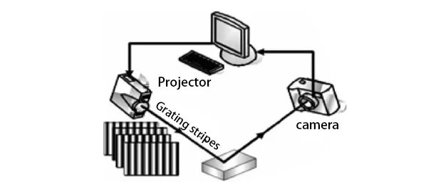
The grating stripes undergo deformation after being modulated by the object’s surface shape.
The degree of deformation depends on the object’s surface height and the relative position of the projector and the camera.
The receiving camera captures the deformation image. The image is handed over to the computer for further processing.
The computer uses the system’s structural parameters for the processing. This allows the measurement of the object’s structural parameters. Finally, the deformation of the object is obtained.
Structured light visual inspection has the advantages of large range, non-contact, fast speed, good system flexibility, moderate accuracy and so on. However, due to the constraints of its principle, it is not favourable to the measurement of objects with complex surface structure.
Fig. 1 Principle diagram of projected structured light 3D measurement system
2.2 Laser triangulation
Laser triangulation is an important form of non-contact optical measurement, which is widely used and the technology is relatively mature.
The principle is that the light source emits a beam of laser light, which irradiates the plane of the object to be measured and then reflects onto the detector to form an image.
When the position of the object surface changes, its image on the detector also occurs corresponding displacement.
By detecting and calculating the image shift, technicians obtain the real object displacement through the relationship equation between image shift and actual displacement.
This method is simple in structure, fast in measurement speed, high in accuracy, flexible in use, and suitable for measuring objects of large size and complex shape.
However, the laser cannot irradiate certain object surfaces, making measurement impossible. Additionally, environmental factors and the characteristics of the measured object’s surface relatively affect the accuracy of the laser triangulation method. Therefore, researchers must vigorously study high-precision triangulation measurement methods.
2.3 Laser ranging methods
Laser has good collimation and very small divergence angle, so that the instrument can carry out point-to-point measurement, adapted to very narrow and complex measurement environment.
The laser distance measurement method uses the characteristics of the laser. The laser signal is emitted from the transmitter and irradiates the surface of the object.
After reflection, the laser travels back along the same path to the receiving device. By detecting the laser signals, either the time elapsed or phase changes can be measured.
This allows calculation of the distance between the laser rangefinder and the object being measured.
Laser distance measurement mainly divides into two categories: pulse distance measurement and phase distance measurement.
For pulse ranging method, its system structure is simple, the detection distance is far, but the traditional ranging system uses direct counting to measure the round-trip time of the light pulse, low precision.
Although the phase ranging system structure is relatively complex, it offers higher accuracy. With the rapid development of optoelectronic technology, engineers have continuously optimized and improved phase laser ranging technology. It now meets the needs for ultra-short distance and ultra-high precision measurements.
With the laser rangefinder towards miniaturisation, intelligent direction, due to the unique advantages of laser distance measurement technology, will have more and more broad application prospects in various types of distance measurement field.
2.4 Interferometry
Commonly, engineers use a laser interferometer with a laser as the light source for the Michelson interferometer. The beam splitter mirror divides the light emitted by the laser into measurement light and reference light. It directs these beams to the reference plane and the target plane, respectively. After reflecting, the two beams overlap at the beam splitter mirror and interfere with each other.
When the target plane moves, the interference pattern’s light and dark stripes change a corresponding number of times. The photoelectric counter records these changes, allowing technicians to calculate the distance the target plane has moved.
According to the different optical paths, there are two types of split optical paths and common optical paths.
Laser interferometry offers very high measurement accuracy and fast speed. However, engineers find its measurement range limited by the wavelength of the light wave. As a result, they typically avoid using it to detect large-scale objects or measure complex surfaces with significant concavity and convexity changes. Instead, they use it primarily to measure small displacement changes.
2.5 Image analysis method
Researchers also call the image analysis method stereo vision, focusing their studies on the geometric size, position, and attitude of the object in space.
Stereo vision measurement is based on the principle of parallax, which is the difference in the position of a point between the corresponding points in two images. By calculating the distance from the parallax of the point, the spatial three-dimensional coordinates of the point can be obtained.
Generally from one or more camera systems from different orientations and angles to determine the distance information from multiple two-dimensional images of the object, the formation of three-dimensional images of the object surface topography, monocular, polyocular vision.
Engineers classify stereo vision measurement as a passive three-dimensional measurement method. They often use it to identify 3D targets, determine object positions, and analyze shapes. Because this method involves a simple system structure, researchers and developers apply it widely in the field of machine vision.
The basic geometric model of stereo vision is shown in Figure 2.
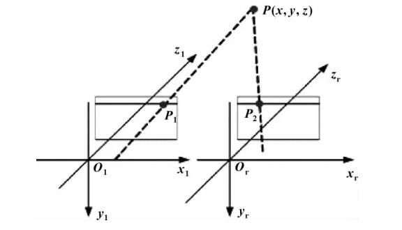
Figure 2 The basic geometric model of stereo vision
Binocular stereo vision uses two cameras positioned differently to capture the same scene. By moving or rotating, it calculates the parallax of points in the two images. This allows obtaining the 3D coordinates of those points.
Its measurement principle is shown in Fig. 3. A complete stereo vision system usually includes six major parts: image acquisition, camera calibration, feature extraction, image matching, 3D information recovery, and post-processing.
Researchers widely use the stereo vision method in aviation measurements and robot vision systems. They focus international academic research on stereo vision challenges such as binocular systems, multi-camera setups, and multi-frame image sequences, making these topics major research hotspots.

Fig. 3 Principle of three-dimensional measurement by binocular stereo vision
Shortcomings
After decades of development, non-contact measurement technology has greatly improved. However, besides the outstanding advantage of not contacting the measurement object, it also has various shortcomings.
(1) The precision is not considered to be high compared to the contact measuring instrument articulated arm, coordinate machine, etc.
Non-contact measurement technology due to the gauge sensor element is not in contact with the measured object, the middle of the interval medium and distance greatly affects the measurement accuracy, the majority of cases the measurement accuracy is lower than the contact measurement technology.
(2) Higher price
Non-contact measurement technology using a large number of high-precision optical and electronic components, the price is too high relative to the contact measurement products, not conducive to the popularity of non-contact measurement technology.
(3) Part of the non-contact measurement methods on the workpiece and the environment have special requirements
Non-contact measurement methods due to its special nature, the workpiece and the environment also have some special requirements. Such as nuclear magnetic resonance instrument can not measure magnetic metal objects, ultrasonic measurement technology for the ambient temperature is more sensitive, and optical measurement technology based on the gauge can not adapt to the harsh working environment.
Development trend
Through the analysis of various non-contact measurement technologies and products at home and abroad, the development trend of non-contact measurement technology mainly includes the following points.
1. Highly integrated
The principle of non-contact measurement technology is mature, but most of the measurement products at this stage have a single function and cannot realise multi-purpose. The future of non-contact measurement instruments will achieve a high degree of integration.
Stereo vision camera, for example, integrated non-contact temperature measurement, displacement measurement, vibration measurement, etc. will greatly improve the applicability of the product, which is conducive to reducing the cost of the purchase of measuring instruments, and accelerate the promotion and application of non-contact measurement technology.
2. High precision and accuracy
At this stage of non-contact measurement technology products are still less accurate than the contact measurement technology, but also need to vigorously develop high-precision optical components, electronic components and excellent analysis and processing software to improve the measurement accuracy of the instrument, in due consideration of the cost of the case, and ultimately be able to achieve a comprehensive beyond the contact measurement technology products.
3. Reduced requirements for the working environment
Non-contact measurement technology relies mostly on optical components, poor environment for the optical components of the work of precision and accuracy has a greater impact, in the poor working environment, optical measurement instruments can not even work properly, which is the urgent need to solve the technical problems, but also non-contact measurement technology, a direction of development.
4. Highly Intelligent
As industrial technology rapidly advances, engineers increasingly require measuring instruments to perform intelligent analysis of measured objects. To meet this need, developers are advancing non-contact measurement technologies toward greater intelligence. For example, modern non-contact measuring instruments can intelligently analyze the object and automatically select the most optimal measurement method.
Conclusion
Non-contact measurement technology has an increasingly wide range of applications in industrial production. Due to the long measuring time required for contact measurement, it is difficult to measure objects with large or small dimensions, complex surface contours or long measuring cycles.
At the same time, with the development of optical technology and electronic circuit technology, the accuracy of non-contact measurement is getting higher and higher, and in some cases the accuracy even exceeds that of contact measurement, so non-contact measurement will become the main measurement method in the field of industrial production in the future.