Bending is one of the most important and widely used techniques in sheet metal fabrication. The basic principle of the sheet metal bending process is to utilize the plastic deformation of metal to produce parts or assemblies of the required shape and size.
In many sheet metal structural products, bending can replace complex components such as welding, riveting, and bolting.
Compared to welding, riveting, and bolting, bending makes it easier to control the shape and size of the plate precisely, and it also has higher accuracy and repeatability, which makes it suitable for the manufacture of various types of small, complex parts.
The bending process requires relatively simple tooling and equipment, mainly including bending machines, molds, etc., equipment operation is simple and easy to start, reducing processing costs and technical barrel.
Compared to welding, this process requires less strict production environments and lower personnel skill levels, resulting in reduced production costs. It allows manufacturers to produce mass quantities quickly and finds wide application in bulk manufacturing across various mechanical industry fields.
Bending processing offers a certain degree of flexibility, resists the effects of varying plate thicknesses, and suits the processing of different plate thicknesses.
Comprehensively speaking, bending is more aesthetic than welding, riveting, and fixing two separate parts together. It also has the advantages of short cycle time and low cost-effectiveness of the product process.
Because of the increasing complexity of bending workpieces, product bending is becoming more and more difficult. Without good process guidance, it will not achieve the desired results.
Due to the increased bending complexity, interference problems are likely to occur, resulting in bending and forming not being fully completed. Therefore, a reasonable bending process plan, bending tooling selection, and tooling design are critical to solving the bending interference problem.
Bending interference problems
Bending conflict mainly exists in two or more bending products, specifically in the bending edge and mold, equipment, or the product itself collision, resulting in regular bending.
The shape of the part, size, mold, equipment structure, and bending order mainly affect this interference.
(1) bending edge and mold interference is mainly in the bending process, the bending edge of the bending rotation, and the upper or lower mold collision interference, resulting in the product not continue to bend or deformation.
This type of bending problem is the most common one, and it is also the first thing that all sheet metal craftsmen need to consider when carrying out bending analysis.
Figure 1 shows the upper die interference, and Figure 2 shows the lower die interference.
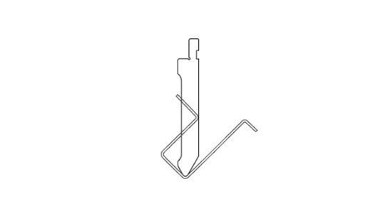
Figure 1 Upper die interference
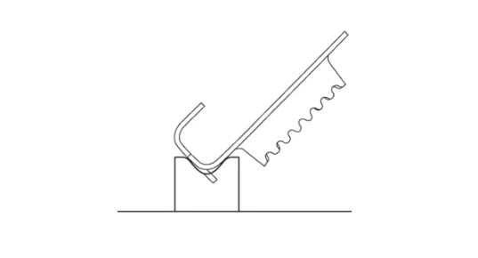
Fig 2 Lower die interference
(2) Product and equipment interference This is often due to several sides of the closed product bending edge being too high, the product being too long, or in the middle of the wider sheet metal folding a ‘Z’ structure.
In three-sided closed bending, as shown in Figure 3, after bending the two parallel sides along the length direction, the product’s bending edges are too high. The bending edges on the parallel sides collide with the upper die, causing interference and interrupting the bending process.
You cannot bend the product in the order of adjacent sides because after bending the first side and folding the adjacent side, the first bending edge interferes with the upper die. When placing the first bending edge at the end of the bending machine, the product’s positioning on the left and right sides of the machine bed and the workpiece edge positioning interfere with the rear stopper device, preventing proper positioning on this bending machine.
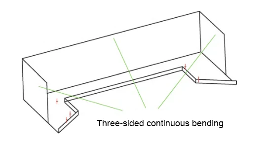
Figure 3 Three-sided closed bending
Figure 4 shows ‘Z-shaped bending,’ which looks like a simple ‘Z’ bending structure, but whichever bending edge you bend first, you cannot bend the second bending edge afterward.
After completing the first bending edge, the product forms a large ‘L’ structure. Because the heights of the two ‘L’ sides are too large, when folding the second bending edge according to the bending direction, the first bending edge faces downward and interferes with the bending machine table surface. Interference problems.
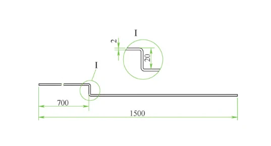
Figure 4 ‘Z’ bending
(3) Interference between the bending edge and other structural features mainly occurs in products that require a strict fit.
This is mainly found in products that have a strict fit relationship. Due to the accumulation of errors in the bending process and factors such as bending spring back, the product bending interference and angle bending is not in place.
Figure 5 shows the assembly structure of the bending. The position marked by the red circle indicates the bending location. If the negative tolerance of the bending width is too large, the collision and interference between bending edge 1 and bending edge 2 will occur, preventing them from closing properly. Therefore, you must leave a specific gap at position 3; otherwise, bending edge 2 cannot maintain the 90° angle.
Bending interference problems are complex and varied, and it is impossible to list all cases; the above mainly lists some common cases for reference.
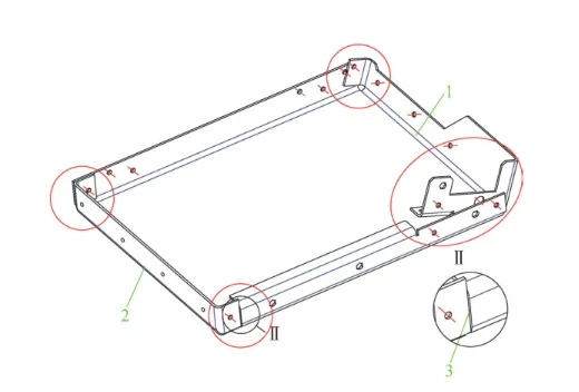
Figure 5 Bending with an assembly structure
Solutions
(1) Choose molds reasonably and reshape mold structures; the bending hook mold is the most commonly used mold to prevent bending interference.
This mold structure can well avoid the interference problem of a ‘U’ shaped bending structure, according to the bending edge’s size. The bottom edge of the ‘U’-shaped product can be selected or designed accordingly to engage with the hook die (see Figure 6).
In addition to the hook die, reshaped bending dies are a common way to prevent bending interference.
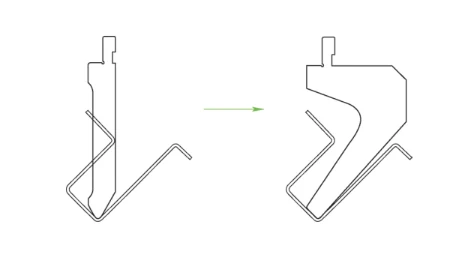
Fig 6 Hook bending die
Mold reshaping takes various forms, and designers analyze them according to the product’s interference. They may reshape the upper or lower mold by processing notches, holes, and other features on the mold.
When reshaping the bending mold, designers should fully consider the mold’s strength after reshaping to meet usage requirements. If the mold notch or hole is too large, the mold may easily deform, significantly reducing its service life and failing to guarantee the product’s accuracy. Figure 7 shows the reshaped mold.
Fig 7 Conforming mold
Sometimes, the bending hook mold cannot avoid bending interference, so technicians add the pressure line (or planing groove bending) process to address this issue:
First, technicians mark the bending line or machine a ‘V’ groove at the bending position. They typically control the groove depth at 80% of the plate thickness. The groove angle is designed to be 2° greater than the final forming angle to account for material springback during bending, allowing better control over the final angle. (Reserve a gap of 2 ° to facilitate processing control angle). The crimping process is shown in Figure 8.
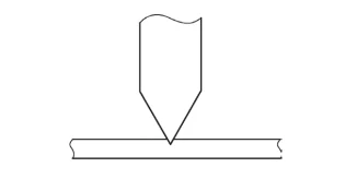
Figure 8 Press line process
Operators first fold the initial bending line to a certain angle to avoid tool interference during subsequent bends. They then press the bending edge to 90°, as illustrated by the grooving and bending process in Figure 9.
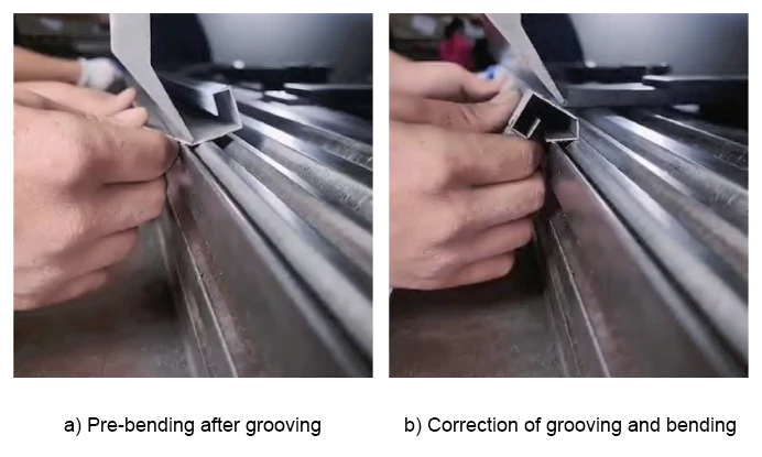
Figure 9 Slotted bending
In general, engineers can apply the pressure line process to structures that cannot be bent in a single operation. During the second bending, the pressure line guides the new bend to accurately follow the original bending line. Otherwise, it is prone to the second bending bias problems, or bending angle control is not a good phenomenon.
The planing groove bending process has a disadvantage: it is prone to bending fractures. Therefore, this process should be carefully judged and selected based on specific processing needs.
(2) Reasonable arrangement of bending process route In many cases, a reasonable bending process sequence can greatly reduce the bending interference and the need for special mold requirements.
For example, in the bending shown in Figure 4, first pre-bend one 90° edge to about 135° (see Figure 10). Next, bend the second edge to 90°, then finish by bending the 135° edge back to 90°. This completes the product bending.
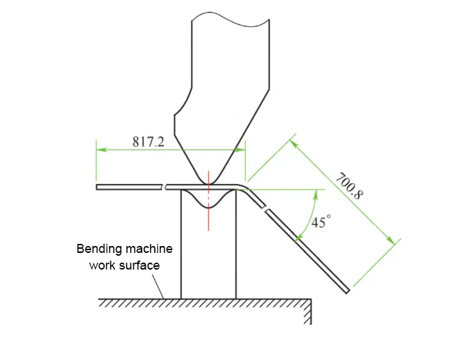
Figure 10 Pre-bending schematic
In the bending interference shown in Figure 5, a reasonable bending sequence is a key factor in determining whether the workpiece can be processed.
For analyzing the bending order of multiple edges and complex parts, use reverse thinking. Start by identifying the last bend to avoid interference, then analyze the second last, and continue backward.
In Figure 5, bending edge 1 and bending edge 2 must be the last two bends. Otherwise, the upper die cannot reach the red-marked four corners. This causes the workpiece bending order shown in Figure 11.
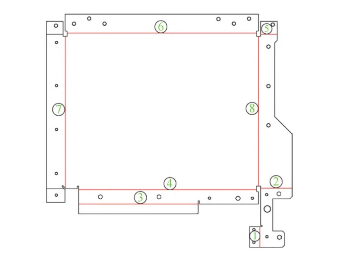
Figure 11 Bending sequence
Increasing the pre-bending process is also an effective solution to the common measures of bending interference. The method adds bending interference at the reverse bend location. The angle is kept moderate according to the level of bending interference. Figure 12 shows the pre-bending process.
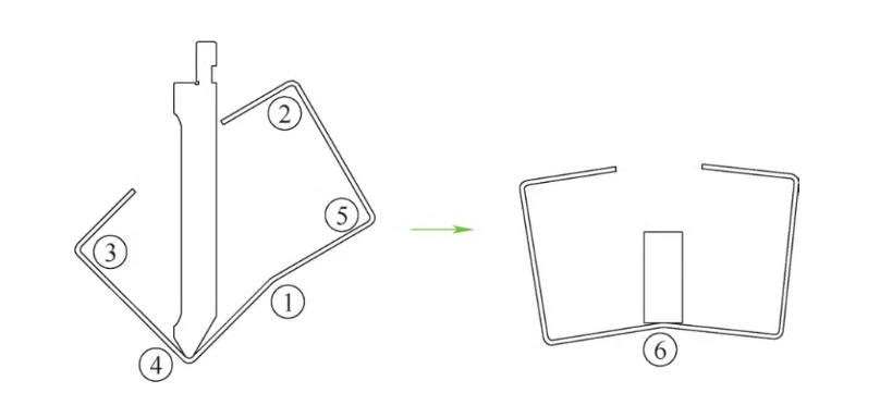
Figure 12 process pre-bending process
(3) Select the appropriate bending equipment With the rapid development of equipment, bending equipment has become a variety.
Different processing methods divide the bending machine into upper bending and lower bending types.
Upper bending type bending machine pressure plate on the top, suitable for thin plate bending;
The downward bending type bending machine pressure plate below suits thick plates and large workpiece bending.
To analyze the bending process effectively, you must fully understand the equipment’s performance. Key factors include structural features, stroke length and height, backgauge stroke, and worktable width. These parameters directly affect bending interference.
(4) Design of special bending mold structure
For the complex structure of the bending workpiece, often need to make special non-standard molds according to product design. Non-standard mold structures take various forms; some feature a single shape (see Figure 13), while others combine multiple components of the motion mechanism.
Figure 13 non-standard single-shaped mold
(5) Optimise bending structure design
Some sheet metal product designs focus mainly on performance, function, and appearance. However, their structures may lack good manufacturability.
For this sheet metal bending structure, it is necessary to optimize the bending edges and welds. This approach maintains the original product structure, size, and performance while improving manufacturability.
Figure 14 shows the structure of a locomotive lampshade, which is a first bending, then welded three-sided structure, bending edge ① and bending edge ②, and the bottom plate at an acute angle in the absence of a unique mold, it is challenging to achieve bending.
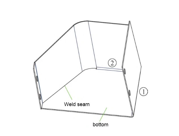
Figure 14 A locomotive lampshade structure
We optimized the weld and bending edges by redesigning the original weld edge into a bending edge. We also converted bending edge ② into a weld. This change immediately improves manufacturability.
Firstly, this instantly reduces the bending difficulty and solves the bending interference problem;
Secondly, shortening the weld length to 55% of the original reduces costs and improves efficiency.
Summary
This paper lists bending product structures as simple. It explains bending principles and interference from different angles. It proposes process solutions and applies them in practice.
The bending process is an efficient study, and manufacturing will continue to encounter various new problems. To solve bending interference, we must consider production, manufacturing, cost, and cycle time. Selecting the right program improves quality and efficiency.