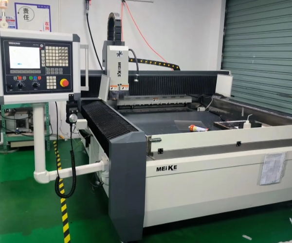
With the rapid advancement of computer technology, EDM technology has become a cornerstone of modern manufacturing, especially in CNC wire-cutting machines. EDM wire cutting now dominates the field, accounting for 60% of all EDM machines. As digital technologies evolve, taper cutting has become a fundamental capability in wire-cutting machines, extensively applied in mold-making, part manufacturing, and producing complex-shaped bodies.
Although technicians widely use taper machining, they face the challenge of ensuring high levels of control and precision. They must maintain accuracy and stability in taper cutting. In this article, we will explore the principles, equipment structure, and programming methods of CNC wire EDM taper machining while offering insights on how to improve its precision and efficiency.
Taper Cutting Device of CNC Wire-Cutting Machines
In CNC wire-cutting machines, a taper wire frame achieves taper cutting. There are two main types of taper wireframes: translating taper wireframes and swinging taper wireframes. Each design offers specific advantages and suits different taper angles and accuracy requirements. The choice of which device to use depends on the taper angle and the precision needed for the job.
1. Translating Taper Wire Frame
The translating taper wire frame is one of the most common devices for taper cutting. It features a simple design and operates with an intuitive working principle, making it ideal for cutting small tapers with high efficiency. The core operation involves controlling the tilt angle of the electrode wire through the relative movement of the upper and lower guide wheels. The lower guide wheel remains fixed, while the upper guide wheel moves in the U and V directions via a cross-drag plate driven by a stepper motor. As the guide wheel moves, the angle of the electrode wire changes, resulting in the desired taper.
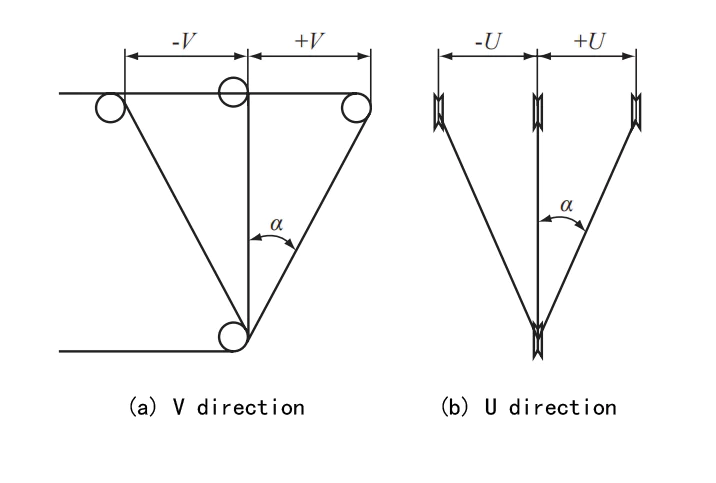
Fig 1 U and V direction translation sketch of the upper guide wheel
(1) Principle of Operation
Lower Guide Wheel: Fixed in position, typically located at the bottom of the cutting area, providing support for the electrode wire.
Upper Guide Wheel: Driven by a stepper motor, it moves in the U and V directions.
Cross Drag Plate: Connects the upper guide wheel to the motor-driven section, ensuring smooth, stable movement between the guide wheels.
As the upper guide wheel shifts in the U and V directions, the electrode wire’s angle changes, creating a taper. The greater the distance the guide wheel moves, the larger the angle of offset, which alters the cutting path and forms the required bevel. Because of its simple design and minimal mechanical complexity, the translating taper wire frame is particularly effective for precise small taper machining (≤6°).
(2) Advantages
Simple Structure, Easy Maintenance: The translating taper wire frame features an intuitive design that relies on straightforward translation and stepper motor control. As a result, it has a simple structure, making it easy to operate and maintain.
Ideal for Small Tapers (≤6°): Due to its precision and ease of operation, this device excels in machining small taper angles. It is particularly suitable for high-precision applications like mold manufacturing and precision parts production.
(3) Disadvantages
The translating taper wireframe typically restricts the maximum taper angle to 6°. If the taper angle exceeds this limit, the electrode wire may experience deformation beyond the elasticity of the tungsten-molybdenum wire, causing it to slacken or even break. This leads to a loss of machining accuracy and unstable cutting results.
Risk of Electrode Wire Stretching or Breaking: For larger taper angles, the translating wire frame may struggle to control the tension and elongation of the electrode wire effectively. This can cause the wire to break or slacken, negatively impacting cutting quality and reducing machining efficiency.
2. Oscillating Taper Wire Holder
The Oscillating Taper Wire Holder employs a more advanced mechanical design specifically built for machining large tapers (greater than 6°). Its core function is to control the movement of the upper and lower wire arms using a four-link mechanism. This mechanism ensures constant tension between the electrode wire and the guide wheel, preventing overstretching and instability. Unlike the translational taper wire holder, the oscillating design allows for a wider range of adjustments in the electrode wire angle through the oscillation of the wire arms, ensuring smooth and accurate cutting even with larger tapers.
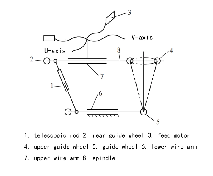
Fig. 2 Schematic diagram of oscillating taper wire holder
(1) Principle of Operation
Four-link mechanism: This is the heart of the oscillating taper wire holder. By controlling the movement of the four connecting rods, the mechanism ensures that the upper and lower wire arms translate and oscillate in perfect synchronization, maintaining stable motion for the electrode wire in the guide wheel.
Oscillation of upper and lower wire arms: The system maintains synchronized movement of the electrode wire in both directions relative to the guide wheel. The four-link mechanism’s parallelogram motion ensures the wire does not over-extend or slacken, even with large tapers.
Stability of the electrode wire: Because the wire does not stretch or slacken, as it does in the translational design, the oscillating taper wire holder maintains a stable tension throughout the cutting process. This stability minimizes the risk of the electrode wire breaking or the cut being inaccurate, even when working with larger tapers.
(2) Advantages
Ideal for large tapers (>6°): The oscillating taper wire holder excels at controlling the electrode wire angle with high precision, making it perfect for cutting large tapers. It ensures consistent cutting results, regardless of the taper’s size.
Enhanced machining stability: The oscillating mechanism prevents issues like electrode wire stretching and relaxation, providing superior stability during the cutting process compared to the translational wire holder. This makes it ideal for mass production and for machining high-precision parts.
Reduced electrode wire wear: Because the electrode wire experiences less stretching and breakage, it wears less over time. This reduces the need for frequent replacements, ultimately improving machining efficiency and reducing downtime.
(3) Disadvantages
Complex structure and high cost: The four-link mechanism is intricate and requires more components, which increases the cost of manufacturing and maintenance. The additional complexity also demands more precise tuning, which can make it more expensive than simpler systems.
Higher operational requirements: The complex mechanical design requires operators to have specialized knowledge to use the system effectively. For those unfamiliar with the equipment, a longer learning curve and more extensive training may be necessary.
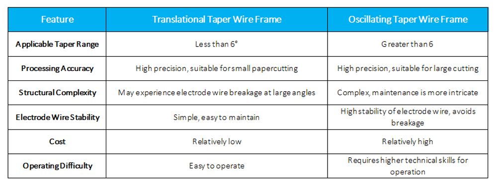
Table 1 Comparison of taper machining methods for CNC wire EDM machines
Forms and Applications of Taper Cutting
In CNC wire cutting, taper cutting typically takes two forms: standard fillet cutting and upper and lower profile cutting. Choosing the appropriate method based on the workpiece’s requirements can significantly enhance both processing efficiency and precision.
1. Standard Fillet Cutting
Standard fillet cutting maintains a fixed taper angle across the entire cutting contour and is widely applied. During processing, the programming system sets the cutting angle, and the machine automatically performs the required cutting task. This method is ideal for workpieces that don’t have complex shape requirements. One thing to note is that at the rounded corners, the radii of the upper and lower contours may differ because the four axes—X, U, and V—need to make uniform movements.
2. Upper and Lower Profile Cutting
Upper and lower profile cutting is a more intricate technique, suitable for workpieces with complex geometries. By linking the four axes in uneven motion, this method generates workpieces with varying contour surfaces. Upper and lower profile cutting includes several subtypes, such as ISO fillet cutting, variable skew cutting, and upper and lower contour dissimilarity cutting. These methods primarily rely on the capabilities of advanced programming software, which ensures high accuracy and stability during machining.
Application Examples:
ISO Fillet Cutting: This method processes workpieces where the fillet angles of the upper and lower contours are identical.
Variable Slope Cutting: This approach applies to workpieces where the geometric elements of the upper and lower contours match.
Upper and Lower Contour Dissimilarity Cutting: This method is suitable for situations where the upper and lower-end face contours have different geometric elements. It often serves to manufacture more complex parts that require a high degree of precision.
Computer Programming Methods for Taper Cutting
Computer programming plays a crucial role in achieving accurate taper cutting on CNC wire EDM machines. Taper-cutting programs typically follow two main approaches: standard fillet cutting and upper and lower profile cutting. Although these methods differ, both rely on the support of a four-axis linkage system to ensure precise and efficient machining.
1. Computer Programming for Standard Fillet Cutting
Standard fillet cutting is a relatively simple method, often used for smaller tapers. The programming process is straightforward, beginning with the creation of a program based on the two-dimensional profile of the workpiece’s lower surface. The program adjusts the taper parameters and generates a four-axis linkage machining routine. The steps are as follows:
Define the Lower Surface Contour:
Design a 2D contour drawing of the lower surface based on the actual size of the workpiece.
Set the Taper Parameters:
Skew: This refers to the tilt angle of the molybdenum wire. It can be positive or negative. A negative skew occurs when the workpiece is smaller at the top and larger at the bottom, and a positive skew is the opposite.
Scale: Scale refers to the distance between the upper and lower guide wheels or the distance from the center of rotation to the center of the upper guide wheel (in millimeters). Proper scale settings ensure accurate electrode wire movement and machining precision.
Base Surface: The base surface corrects for the difference in height between the lower guide wheel and the workpiece’s cutting surface. It represents the distance from the lower guide wheel (or rotation center) to the lower surface of the workpiece.
Generate the Four-Axis Linkage Program: After inputting the parameters, the system automatically generates a four-axis linkage machining program suitable for standard fillet cutting.
This method works best for small tapers (usually under 6°) and allows for precise, fine cutting with a simple and easy-to-understand program.
2. Computer Programming for Upper and Lower Profile Cutting
For more complex machining tasks, such as upper and lower profile cutting, the programming process becomes more intricate. This involves designing and processing three-dimensional shapes. The program must account for both the lower and upper surfaces simultaneously. The process typically includes the following steps:
Design the Lower Surface Contour:
Create a 2D contour drawing for the lower surface and define the machining trajectory. We save important details, such as the position of the fillet hole, starting point, cutting direction, and compensation amounts, as subroutines.
Design the Upper Surface Contour:
Design the machining trajectory based on the 2D contour of the upper surface. Ensure that the corresponding points of the upper and lower end faces match and that the number of geometric elements is consistent. Pay special attention to the geometric symmetry between the two end faces.
Four-Axis Synthetic Programming:
Input the workpiece thickness, wireframe height, base surface, scale, and other parameters. Then, call the upper surface program. The system will automatically generate a machining trajectory that aligns the upper and lower contours, ensuring precise synchronization of the four-axis motion.
For four-axis synthetic programming using ISO fillet cutting or variable skew cutting methods, you must meet the following conditions:
The number of program strips for the upper and lower sides must match.
The program must align the strips across the upper and lower sides.
The compensation amounts and machining direction must be consistent.
Generate the Main Program:
After completing the four-axis synthesis, generate the final program. You can then save it, send it to the console, print it, or convert it into an NC program for further execution.
Execute the Cutting Process:
The operator inputs the program into the CNC machine’s console, which then follows the instructions to perform taper cutting.
3. The Role of Programming Software and Control Systems
The success of taper cutting relies not only on accurate mechanical design and programming but also on the seamless cooperation between programming software and the control system. Modern programming software, with its robust three-dimensional modeling and path-planning capabilities, simplifies the execution of complex upper and lower-profile cutting tasks.
Different CNC wire EDM machines come with varying software systems. Advanced systems provide more efficient four-axis programming tools, enabling manufacturers to process even complex workpieces effectively. By optimizing cutting paths and adjusting cutting parameters, these software systems significantly improve machining efficiency, reduce wear and tear, and minimize errors caused by programming inaccuracies.
Conclusion
Taper cutting is a critical technology in CNC wire-cutting. The machine structure, programming software, and control systems are closely tied to its accuracy. Both the translational and oscillating taper wireframes offer unique advantages, and selecting the right device and programming method is crucial for improving efficiency and precision. As technology continues to advance, the accuracy of taper cutting will improve even further, enabling broader industrial applications.
